
Liquid Crystal Displays
Copyright © by V. Miszalok and V. Smolej, last update: 2007-06-07

Let me know
what you think
| Home | Index of Lectures |
|
Liquid Crystal Displays
|
Let me know what you think |
1888 Rheinitzer, a botanist from Wien, discovered liquid crystals.
1963 Physicist Williams discovered the influence of electrical fields on the transparency of liquid crystals.
1968 Heilmeyer built the first lab-quality LCD.
1973 Sharp in Osaka began with the mass production (ca. 40% of the worldwide production today).
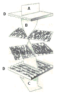
1. A polarization filter, consisting of parallel grooves, transmits only the light, which is polarized in the direction of the grooves.
2. Two parallel polarization filters with grooves, which are at 90 degrees to each other, are opaque to any light.
3. If you fill the space between the parallel filters with the Cholesterine-based macro-molecules of elongated shape, they will align themselves along the grooves. Between the two orthogonal polarization filters they will orient in the interstitial space in a staircase, helical way . This molecular order is able to rotate the polarization in small steps resulting in an overall re-polarization of 90 (or even 180, 270 etc) degrees and light can pass through the orthogonal front filter. The yield is low (approx. 4-8%) but none the less not negligible. LCD-displays are spontaneously transparent. When they are backlit they look bright, when in zero-voltage condition.
4. If a strong enough voltage is applied, the molecules will orient along the electrical field lines and will thus lose the capacity of rotating the polarization plane. The oriented molecules behave optically speaking like a vacuum. Backlit display turns black under the tension.
5. By adjusting the voltage level it is possible to control the amount of light coming through:;
| no voltage | light comes through | white pixel |
| intermediate voltage | light is partly obscured | gray pixel |
| maximum voltage | light is closed off | black pixel |
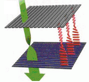
| Liquid crystal as an electrically switchable light valve Graphics from: FAZ, Article by K. Tetzner 1999 light direction up to down corresponds to the back to front direction of a display |
| Spontaneous condition, no external voltage applied |
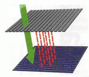
Condition with external voltage applied |
 |
 |
| A: unpolarized light source on the rear of the display B: 0 degrees polarized light enters the display C: 90 degrees polarized light leaves the front of the display D: grooves polarization plates |
The elongated molecules orient themselves along the electric field loosing their helical arrangement. The cell is opaque to the incident light. |
| Download the good article: T. Kaltenbach (deutsch PDF 56kB) The drawings below are extracted from this article: PC Professional 3/2000, Ziff-Davis Press |
 |
 |
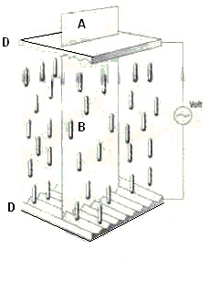
A plastic grid divides the space between the polarization filters, which is filled with liquid, into rows and cells. The rectangular compartments are called "nematic cells" and constitute the physical pixels of the display.
The pixels are sandwiched between a layer of vertical (hind side) and horizontal (front side) wires. Every crossing point can be used to apply the voltage. The signaling is done via a multiplexing hardware. First a current line wire is set under tension and then, from left to right, the vertical wires corresponding to pixels, that are supposed to stay dark, are set under tension as well. Then the line voltage is dropped back to zero level and the process is repeated for the following line. Given a refresh interval of T and number of pixels N the switching time is 1 / (T*N) [sec] pro Pixel. The shorter the pixel switching time, the high must the voltage that is needed to change the staircase structure of crystals. However, the voltage is applied along the complete length of both the vertical and horizontal line, not only at their cross-over.
At some limiting voltage both the current line and the current column will appear noticeably darker, an effect known as cross talk. To avoid it, the voltages should not surpass this limiting level, which however limits the brightness of the resulting image and its contrast. The opto/electrical design of present-day monochrome LCDs have been highly optimized to provide a good contrast at a negligible level of cross talk. These technologies bear names like Super Twisted Nematic LCD = STN and Double Super Twisted Nematic LCD = DSTN. It has been proven, that it is impossible to control more than about 200 000 Pixels using this technology.
In other words this approach is not feasible for LCD-Monitors and can be used just for mini displays. There's a way around this problem: you can arrange several smaller displays in a matrix fashion to give an impression of a bigger monitor. The transitions between individual frames, however, can not be eliminated. For color LCDs with a sharp contrast and tolerable cross-talk a completely different approach must be found.
Thin Film Transistor Technology:
At any cross-over point a field effect transistor is built, which on a given signal creates an electrical field, that stays on for as long as required, i.e. until another signal turns it off. To hamper the light properties as little as possible one etches the transistors out of thin, translucent semiconductor wafers (of the display size) - hence their name = Thin Film Transistor or TFT for short. This kind of LCDs is also called Active Matrix LCDs = AMLCD; this does not mean of course, that AMLCD cells do emit light. Like any other LCD they need incident external light. The expression "Active" applies only to the voltage supply of cells: in the case of color-LCDs it is supplied by TFT building blocks (=large-surface, thin-layer semiconductors)
The production of these semiconductor layers, which are several hundred sq. centimeters in size is technologically very demanding. The production is extremely error-prone and its yield correspondingly low.
Most important LCD producers worldwide are Sharp Osaka, Toshiba Tokyo, and NEC Niigata, although the American firm RCA was the first who developed LCD displays (without TFT) and well into the seventies the LCDs were exclusively produced in US. The US government is trying hard to bring the LCD technology back to United States, for instance by generous subsidies of the US Display Consortium in San Jose, CA, a common enterprise of 11 US producers, which in concert try to catch up with the Japanese competition.
LCDs emit nothing, they need foreign light. There are three illumination methods:
1) Normal Daylight suffice to read off a LCD. A mirror foil behind the back polarising glass plate reflects the incoming light. Daylight has to cross the LCD twice: at first from front to the backside mirror foil and to the front again.
Advantage: Daylight is free of charge and needs no battery.
Disadvantages: no color, just dark or bright, no reading at night.
Sample: digital wristwatch
2) Artificial Homogenous White Light behind the LCD can be produced a) by several flat fluorescent tubes or b) by white light emitting diodes (LEDs) behind a milk glass plate, which scatters the light. Strong white light is needed to filter colors by R-, G- and B- filter foils in front of the nematic cells.
Such LCD-TFT-Color displays need a triple number of pixels. The columns are covered by thin red, green and blue filter layers. The pixels have an upright format. For the user three adjacent single pixels blend together much in a similar fashion like in the case of phosphor triples of shadow mask color CRTs. This also means that in a case of a color LCD with a spatial resolution of 1024x768=786.432 the number of pixels to be controlled equals 3x1024x768=2.359.296, which is definitely impossible without the TFT technology.
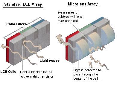
The filters decrease additionally the light yield, so that only 4-6% of the light comes through and 96-94% is spent to heat up the display (which means expensive and intricate methods must be used to cool it). Micro lenses can be used to improve a little on the energy balance and the contrast.
Advantage: The LCD seem to shine.
Disadvantages: high energy consumption, energy saving measures necessary.
Samples: handy, notebook etc.
3) RGB-Flasher is a rectangular plate carrying a mixture of red, green and blur light emitting diodes (LEDs). The plate is triggered to emit a rapid sequence (3-fold refresh-frequency) of pure red, pure green and pure blue light (Field-Sequential-Technology).
Advantages: high spatial resolution, because each pixel emits the three primary colors, no filter foils necessary, low energy consumption, bright, saturated colors.
Disadvantages: danger of flickering, needs extremely fast liquid crystals (OCBs), expensive.
Sample: High-End Notebook
| Microlens Technology to Improve Brightness of Artificial Homogenous White Light LCDs Active-matrix LCDs have a tiny transistor above each cell that turns the electrical field on and off. The transistors are opaque and prevent a portion of light from passing, thus reducing brightness. Tiny lenses behind each cell gather the light and steer it through the cell opening, avoiding the transistor. The result is a brighter image. Both pictures show the light coming from the rear. Picture from PC Magazine 2/2000 |
 |
1. bad contrast: maximum difference between bright and dark is 1:20, often just 1:5.
2. bad legibility when observed from the side
3. not self-illuminating: LCDs need foreign light
4. the energy balance is bad (incoming / outgoing light energy app. 100 : 4).
5. slow: fast moving graphical objects, for instance the mouse, exhibit a trail.
6. LCDs function only in a narrow temperature interval of -5 to + 70 deg. Celsius. That means that LCDs in car instruments, radios etc. must be continually heated.
7. It is impossible to make TFT-Displays bigger than the size of the wafers used to produce the TFT. That means that LCD monitors bigger than 15 inch are extremely expensive.
| top of page: |