Light is electromagnetic radiation with wavelength between 380 nm = blue and 780 nm = red.
Unit 1 nm = 1 billionth of a meter.
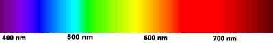
visible light spectrum
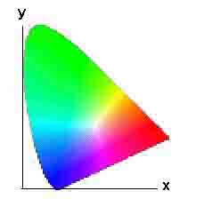
One can mix freely pure spectral colors. The complexity of all kinds of different color mixtures was substantially simplified in 1931 by Commission Internationale de l'Éclairage CIE, who defined a two-dimensional, horseshoe-like color space, that allows easy definition and description of color mixtures. The edge of the horseshoe includes all the pure spectral colors. The inside region contains the mixtures.
The human visual perception is too complex to be quantified in a more than approximate manner. One practical approach is to define 2,3 or more spectral colors and create mixed colors by adjusting the relative proportions of the said spectral colors and colorless (i.e. white/black) component,. Or one defines first the mixed color, quantifies first its colorless (brightness/darkness) component and then codes the color information as deviation in the direction of 2, 3 or more spectral colors. Typical examples would be the RGB and YIQ systems respectively.
It would not be practical to use the same metrics for RGB-Monitore, printers, TV screens or even for nonelectronic purposes (for example car paints). It is better to use different simple basic blocks (never more than 3 or 4) for every one of these applications. This leads to different coexisting color models for different purposes and applications. The models are interchangeable through linear transformations.
 
|
Shadow Mask Color CRTs consist of Red/Green/Blue triples, which are selectively excited through three cathode rays (accelerated through 3 separate anode voltages) Each combination of the voltages applied creates its own characteristical color, so it is natural to characterize different colors through the intensity ratios. The Shadow-Mask-Color-CRTs can not show all the colors, that a human eye can perceive. On the other a significant portion of possible colors can be comfortably described by the three RGB values. This simple color coding has accepted elatively fast and ound its way into all operating systems, image formats and programming languages. The acceptance level is also one of the reasons for use of this technology in all flat panel displays. The final result is that the RGB model is the most important and universal color coding convention. The RGB model may be satisfactory for display purposes, but unfortunately has limitations, which make it less than useful for applications, where the color is not supposed to depend from the display used to create or display it.
3D-vector space of the RGB-color model
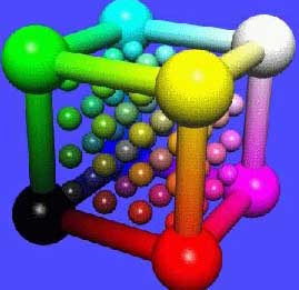 | |
The additive primary colors are red, green, and blue
Mixing green with red creates yellow.
Mixing blue with green creates cyan.
Mixing blue with red creates magenta.
The sum of all three primary colors creates white. |
| Bioengineering Research Group, Univ. of Auckland NZ | | |
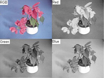
RGB-images contain 3 monochrome images,
the first being fed to the red electron gun of the shadow mask color CRT,
the second into the green and
the third into the blue gun.
An active image display must fill its dark surface with light, i.e. combine the red, green and blue components into the final colors. When all three primary colors are added in equal proportions, a white color results.
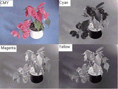
A printer creates the colors the opposite way: it must create colors by eliminating - i..e. subtracting - the red, green and blue colors from the white paper background. By subtracting equal proportions of the primary colors a black color can be created. To achieve this one needs Cyan, Magenta and Yellow, colors which are complementary to RGB. The resulting CMY model is a straightforward complement of the RGB-Modell. The conversion from RGB into CMY is given by the following equations:
C = 255 - R; M = 255 - G; Y = 255 - B;
3D-vector space of the CMY-color model
CMY-image
In case of an ink jet printer the upper right image is drawn using cyan ink,
the lower left using magenta
and the lower right using yellow ink.
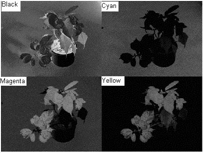
Color printers use usually black paint additionally to C+M+Y colors. This way one can use them also in a black and white mode. Additionally one can effectively apply the black color in color scenes. One can spare the color inks and print black using the black ink, instead of combining color inks. For this reason the color printers use the CMYK model, which additionally to CMY uses also black. The letter K in CMYK stand for the last letter of Black.
CMYK-image used for ink jet printers:
The upper left image is drawn using monochrome black ink,
cyan ink upper right image,
magenta ink lower left image
and yellow ink lower right.
All images together are darker than in the CMY-Model reflecting the low consumption of any ink.
In TV broadcasting the color is for all practical purposes an addition to the black and white information, provided by the so-called Y-signal:
Y = g1*R+ g2*G + g3*B
where g1+g2+g3 = 1.0. Two additional low-bandwidth signal pathways transport the color information in a form of weighted difference between the real signal and the Y component.
YIQ:
is used in color TV norm NTSC (America and Japan).
Y-chanel = Y signal
I-chanel = weighted difference between "redness" and "blueness"
Q-chanel = weighted sum of "redness" and "blueness"

Y = g1*R + g2*G + g3*B      Y-Bandwidth 4.2 MHz
I = g3*(R-Y) - g4*(B-Y)     I-Bandwidth 1.2 MHz
Q = g5*(B-Y) + g6*(R-Y)     Q-Bandwidth 0.6 MHz
YUV:
is used in the PAL colorTV norm (Europe, Africa, Asia except for Japan, Australia) and in digital video. YUV uses similar signals as YIQ (with different weights, however, and using a coordinate system, rotated 33 degrees) but with a higher bandwidth and correspondingly higher quality.
Y-chanel = Black and white signal                               Y-Bandwidth 5.5 MHz
U-chanel contains the difference of two weighted differences    U-Bandwidth 1.3 MHz
V-chanel contains the sum of two weighted differences           V-Bandwidth 1.3 MHz
HLS, HSV, HVC
These color models reflect the human color vision better than the RGB, CMY, YUV and YIQ models, which are targeted primarily for hardware applications. HLS, HSV, HVC are better suited for human than for electronic communication.
HLS is the abreviation for Hue-Lightness-Saturation.
The HLS-Model can be best understood by an analogy of a painter deciding for a color he or she will apply:
(1) choose first a pure color (=Hue).
(2) add white pigment to it, so that it loses a little of its individuality (=Saturation).
(3) Now add the black pigment, so that the color is not too bright (=Lightness)
The three coordinates H, L and S of this system can be easily visualized as follows:
Pure colors are found at the outer border of a horizontal color circle. The hue can be interpreted as the polar angle, going from red (0 degrees), green (120), blue (240) back to red.
The circle is closed to the outside, on the other side any point within the circle stands for some color. The closer to the center of the circle the higher the proportion of the white color. The center of the circle is colorless white.
Below this level other color circles are positioned in a cylindrical fashion. The lower they are, the darker they get. Descending along the vertical axis of the system from its top down to the bottom, one crosses from bright white color down to complete black. Off-axis, for instance for hue=red, one descends from bright red down to dark red, with the degree of color saturation depending on how far off-axis we are. Note that bright red is not as bright as bright white, which, additional to bright red, also contains bright green and bright blue.
This is why the final form of an HLS system consists of two tops (rotational pyramids), with their bottom sides glued together. The top point denotates absolute white, the bottom absolute black and the middle circle a circular approximation of all available colors at an intermediate intensity.
The Hue coordinate is described by an angle between 0 and 360 degrees, the Lightness (vertical axis) and Saturation (radial distance from the Lightness axis) with values between 0.0 and 1.0. The maximal color saturation possible depends on Lightness. Halfway from the top (L=0.5) the maximum saturation (in other words the radius of the circle) is S=1.0. The red color for instance thus has coordinates like H = 0 Degrees, L = 0.5 and S = 1.0.
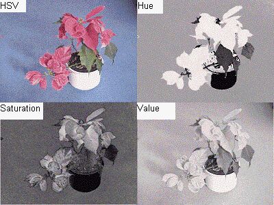
HSV is an abbreviation for Hue-Saturation-Value.
This system is identical to HLS, just that instead of Lightness the vertical coordinate is named value
HVC is an abreviation of Hue-Value-Chroma.
This is a practical color coordinate system, designed about 1900 by a physicist A. Munsell. It is based on a set of samples, whose production is carefully controlled to ensure repeatability. The samples have been selected in such a fashion that from the point of view of human vision they sample the seeable colors in equidistant fashion. It is good in cases when subjective impression of the color is asked for but less useful in case of technical systems.
|
|
Input, Display and Output devices (Scanner, Display, Printer) need a calibration procedure, if the color is supposed to stay constant across image processing steps. For this purpose the International Color Consortium ICC defined a color-independent color calibration format, the so-called "ICC Profile".
The calibration procedure is bootstrapped through the use of test images, which are scanned, displayed or printed out by the device to be calibrated. At predefined spots the result is quantified using photometers and the prescribed measuring procedure. The differences between the expected and actual results is evaluated to determine the correction profiles, which are then stored and used henceforth. When calibrating the user can target goals (Rendering Intents) of different difficulties:
(1) Absolute colorimetric calibration: all the colors, that the device can display, should match the original 1:1.
(2) Relative colorimetric calibration: same as 1, except that the base color of the medium (for example the color of the paper) is ignored, i.e. eliminated.
(3) Photographic calibration: colors are allowed to shift, but their distances should match human impression.
(4) Maximimum saturation calibration: optimal similarity, even if the color media are fully saturated (for example RGB-representation using three monochromatic laser light sources).
|
|
(1) Charles Poynton, Toronto 1997:
www.poynton.com/notes/colour_and_gamma
(2) Munsell Color Science Lab: http://mcsl.rit.edu
| top of page: |