Code Samples:
Tracing and Encoding Boundaries of Subsets in 2D Images
Copyright © by V. Kovalevsky, last update: 16-04-2006

| Home | Index of Samples | PDF Version of this Page |
Code Samples:
|
 |
|
|
We describe here a simple version of the algorithm applicable to binary images. The algorithm may be easily generalized for segmented colored images. "Segmented" means that the image must be subdivided into a not too large number of connected subsets each of which contains pixels of only one color. In a usual colored images there are thousands of small subsets, each consisting of a single pixel. It is of course possible to encode such an image by the presented algorithm, but this has no practical sense.
We consider the image as a two-dimensional complex containing besides the pixels also cracks and points.
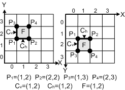 |
Fig. 1. Cells of lower dimensions incident to the pixel F Fig. 1 shows a small image containing the pixel F with the coordinates x=1; y=2; the vertical crack Cv, the horizontal crack Ch and four points P1 to P4. Note that a pixel F and its corner P1, which is the nearest to the origin of the coordinates, have the same coordinates. Also the two cracks incident to F and to P1 have these coordinates. Considering cracks and points along with the pixels makes the understanding of the process of tracing easier. As you will see, it is not necessary to allocate additional memory space for all cracks and points. They should be considered as some kind of virtual cells. |
A crack belongs to the boundary if it lies between a foreground and a background pixel. The end points of a boundary crack also belong to the boundary. The boundary is the set of all boundary cracks and boundary points. It contains no pixels. This is one of the advantages of using cell complexes in image processing: there is no more difference between the boundary of the foreground and that of the background, as this was the case, when defining boundaries as sequences of pixels. The boundary consisting only of cracks and points is a one-dimensional object, representing a thin digital curve, while sets of pixels represent areas and are two-dimensional, which is not suitable for boundaries.
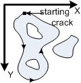 |
Fig. 2. Tracing a boundary component. The image has 4 boundary components The boundary may consist of many connected subsets which are called boundary components. For example, the image of Fig. 1 contains 4 boundary components. It is possible to encode each boundary component by the sequence of the directions of the boundary cracks oriented along the sense of the tracing. |
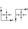 | Fig. 3. The four directions of oriented cracks: in mathematical coordinates (a) an in that of computer graphics (b) Oriented cracks may have only four different directions which are encoded as shown in Fig. 3. Directions corresponding to the code values are different in the mathematical coordinate system (Fig. 3 left) and in that of computer graphics (Fig. 3 right). Direction 1 is always parallel to the positive Y-axis. |
Since there are only four possible directions, the code is very economical: one needs only two bits pro boundary crack. This code (called chain code with 4 directions, also known as crack code) is exact: it is possible to exactly reconstruct the image from chain codes of its components.
We use the following data structure for the chain code of an image:
typedef struct {int X, Y, last, Area;} LOOP;
unsigned char CC[1000];
LOOP Object[100];
The array "Object" contains a record of the type "LOOP" for each boundary component. The record contains the coordinates X and Y of the starting point (see below), the index "last" and the area of the subset included in the boundary component. It is equal to the number of pixels included. The directions of the cracks are stored in the array "CC". It is possible to use one byte for 4 subsequent cracks, but working with bits of a byte is somewhat more complicated. To make the program simpler, we use one byte for each crack. The directions of the cracks of all components are stored in the single array "CC". The directions of the ith component lie between the last direction of the previous component (i-1) and the last direction of the ith component, including the latter one. Thus, the directions are those from
CC[Object[i-1].last+1] to CC[Object[i].last].
If i==0, then the object with the index i-1 does not exist. In this case the sequence of the directions begins with CC[0].
Let e.g. the component with the index 0 contain the directions 1, 0, 3, 2; that with the index 1 the directions 1, 1, 0, 3, 3, 2; and that with the index 2 the directions 1, 0, 0, 3, 2, 2. Then the chain code (we discard in this example the coordinates and the areas) will be:
CC[16]={1, 0, 3, 2, 1, 1, 0, 3, 3, 2, 1, 0, 0, 3, 2, 2};
Object[0].last=3; Object[1].last=9; Object[2].last=15;
The image to be processed by our program must be represented as a one-dimensional array of bytes (unsigned char) of the length NX·NY, where NX is the number of columns and NY - the number of rows. During tracing boundaries some cracks and points must be labeled, as explained below. Therefore we use the bit 0 (the least valued one) for the label of the point, the bit 1 for the horizontal crack and the bit 2 for the vertical one. The remaining bits 3 to 7 can be used for gray values or colors of the pixels. We shall use only the bit 7, since we consider the simplest case of binary images.
To make the tracing subroutine as simple as possible, it is necessary to assign all pixels at the border of the image (the first and the last row; the first and the last column) to the background. In cases when this is not desirable some additional instructions must be inserted into the tracing subroutine.
Before starting the tracing, a starting point must be found for each component (function "Search" below). For this purpose the image must be scanned raw by raw (lines 3 and 5). As soon as two subsequent pixels of different colors (or one background and one foreground pixel) are found (line 8) a candidate for a starting crack C becomes defined as the one lying between the pixels. (The algorithm is slightly simpler if it has to start only at a transition from the background to the foreground, but not at a transition from the foreground to the background). If C is not labeled as already visited during some previous tracing (line 7), then C is recognized as a starting crack of the next boundary component to be traced (line 8). The starting point P is that end point of the vertical crack C, which has the smaller Y-coordinate. Both C and P have the coordinates (x0, y0) of the pixel with the value "val" (line 6). Each time, when "Search" finds a starting point, it calls the function "TraceUni" with the coordinates (x0, y0) of the starting point as arguments (line 9). The function "TraceUni" traces the whole component of the boundary, produces its chain code and returns the value of the included area, as explained below. "Search" returns the number "nComp" of the processed boundary components.
 1. int Search(int Area[])
 2. { int nComp=0, lab, val, valOld, x0, y0;
 3.   for (y0=0; y0 < NY; y0++) //=== Rows =========================
 4.   { valOld=0;
 5.     for (x0=0; x0 < NX; x0++) //====== Columns ===============
 6.     { val=image[x0+NX*y0] & Bit7; // Bit7=128 is global
 7.       lab=image[x0+NX*y0] & Bit2; // Bit2=4; label "already visited"
 8.       if (val && !valOld && !lab)
 9.       { Area[nComp++]=TraceUni(x0,y0);
10.       }
11.       valOld=val;
12.     } //======================= end for (x... ==============
13.   } //========================= end for (y... ================
14.   return nComp;
15. } //*************************** end Search ********************
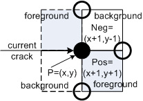 | Fig. 4. To the choice of the next direction The function "TraceUni" (see the code below) steps from one boundary point to the next one along the boundary cracks. To recognize the next boundary crack the function tests two pixels "Pos" and "Neg" lying ahead of the current crack. We use the notions "positive" and "negative" instead of "right" and "left" since the latter must be interchanged when changing from mathematical coordinates to that of computer graphics (compare Fig. 3), while the notions of "positive" and "negative" remain unchanged. Thus our algorithm is directly applicable to both coordinate systems. |
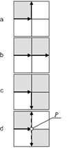 |
Fig. 5. Four possible configurations of the pixels "Pos" and "Neg" The function "TraceUni" calculates the coordinates of the pixels "Pos" and "Neg" by adding the 2D vectors "Positive[direction]" and "Negative[direction]" (see below) to the vector P of the current point, where "direction" is the direction of the current crack (lines 7 to 10). The vectors are predefined as small constant arrays. Then the program gets the values "PosFor" and "NegFor" of the pixels "Pos" and "Neg" from the given image (lines 11 and 12). In the cases of Fig. 5a, b and c the next boundary crack is uniquely defined. But in the case of Fig. 5d there are two boundary cracks each of which may serve as the next crack. (The remaining crack directed to the right is not suitable since the foreground pixel lies on the wrong side of it). To decide which of the two boundary cracks of Fig. 5d should be chosen, it is necessary to know, whether the point P belongs to the foreground or to the background. A point with a neighborhood similar to that of Fig. 5d is called singular. In the first case the two foreground pixels become connected through the point P and the next crack must be directed downwards. Otherwise the two background pixels become connected and the next crack must be directed upwards. |
The membership of P (foreground or background) can be defined by the value of the variable "AllPoints": if AllPoints==0 then all singular points belong to the background; if AllPoints==2 then all singular points belong to the foreground; if AllPoints==1 then the decision about each singular point must be made by the user for each singular point. The function "SingularPoint" being called before "Search" finds all singular points in the image and asks the user for each singular point, whether it belongs to the foreground. The user can make the decision on the grounds of some knowledge about the image. Thus, for example, if it is known, that the foreground contains thin curves, then the singular points in these curves must belong to the foreground to make the curves connected. The function "SingularPoint" encodes the decision in the least significant bit of the byte of the image, which byte has the coordinates of the singular point. The value of this bit will be red by "TraceUni" if "AllPoints" is equal to 1 (line 13).
"TraceUni" calculates the direction of the next crack depending on the two values "PosFor" and "NegFor" (see above) simply by adding 1 or 3 modulo 4 to the current direction (lines 14 to 18). Addition modulo 4 is a cyclic addition, which means addition and computing the rest of the division by 4. The latter operator denoted by % 4 belongs to the standard operators of the C language. These are the simplest substitutes for the following codes:
line 15 for: direction=direction + 1; if (direction== 4) direction=0; // positive turn
line 18 for: direction=direction - 1; if (direction==-1) direction=3; // negative turn
If neither of the conditions of the lines 14 and 17 is true, then the direction remains unchanged: a step straight ahead.
If the new direction is 1, then the running crack is a vertical one lying between a background pixel and a foreground one. This is a crack which the function "Search" is seeking for, as the starting crack of the next component. To avoid that the tracing of one and the same component starts many times, such a crack must be labeled as "already visited". For this purpose the bit 2 of the corresponding byte of "image" is set to 1 (lines 19 and 20).
typedef struct {int X,Y;} iPOINT;
typedef struct {int X,Y,last,Area;} LOOP;
unsigned char CC[1000];
LOOP Object[100];
int iCC=0, iOb=0;
iPOINT Negative[4]={{0,-1},{ 0,0},{-1, 0},{-1,-1}};
iPOINT Positive[4]={{0, 0},{-1,0},{-1,-1},{ 0,-1}};
iPOINT step[4]=    {{1, 0},{ 0,1},{-1, 0},{ 0,-1}};

 1. int TraceUni(int x, int y)
 2. { iPOINT Neg, P, Pos; // P in top. coordinates
 3.   int direction;
 4.   Object[iOb].X=x; Object[iOb].Y=y; Object[iOb].Area=0; //global Object
 5.   P.X=x; P.Y=y; direction=1;
 6.   do
 7.   { Neg.X=P.X+Negative[direction].X;  // Neg is the "negative" pixel
 8.     Neg.Y=P.Y+Negative[direction].Y;
 9.     Pos.X=P.X+Positive[direction].X;    // Pos is the "positive" pixel
10.     Pos.Y=P.Y+Positive[direction].Y;
11.     int PosFor=(image[Pos.X+NX*Pos.Y] & Bit7)==foreground;
12.     int NegFor=(image[Neg.X+NX*Neg.Y] & Bit7)==foreground;
13.     int ObjPoint=AllPoints==2 || AllPoints==1 && image[P.X+NX*P.Y] & 1;
14.     if (PosFor && (NegFor || ObjectPoint) )
15.       direction=(direction+1)%4;     // rest of division; positive turn
16.     else
17.     if (!NegFor && (!PosFor || !ObjectPoint) )
18.         direction=(direction+3) % 4; // rest of division; negative turn
19.     if (direction==1)
20.       image[P.X+NX*P.Y] |=4; // Labeling the vertical crack
21.     CC[iCC++]=direction;     // Record in the Chain-Code
22.     Object[iOb].Area+=P.Y*step[direction].X; // Computing the area
23.     P.X=P.X+step[direction].X; //a move in the new direction
24.     P.Y=P.Y+step[direction].Y; //a move in the new direction
25.   } while( P.X!=x || P.Y!=y);
26.   Object[iOb++].last=iCC-1;
27.   return Object[iOb-1].Area;
28. } // end TraceUni
The current direction is saved in the array "CC" and the index "iCC" is incremented (line 21).
Also the value Object[iOb].Area of the area included into the current component is incremented by the value P.Y*step[direction].X (line 22). As the explanation consider Fig. 6.
 |
Fig. 6. The shaded area of (a) is the difference of the areas (b) and (c) The shaded area of Fig. 6a, being equal to the number of pixels included in its boundary, is obviously equal to the difference of the areas of Fig. 6b and Fig. 6c. The area (b) consists of bars having the width of 1 and the height equal to the Y-coordinate of a point at its lower boundary. Thus the area (b) is the sum of products |
According to the lines 23 and 24 of the above code the current point P moves along the new direction The tracing stops when the starting point (x, y) is reached again (line 25). After that the index iCC-1 of the last direction is recorded in the structure of the current object and the index "iOb" is incremented. The function returns the area of the current component.
int SingularPoints()
{ int cnt=0, act, left, bot, botleft;
  for (int y=0; y < NY; y++) //============================================
  { botleft=left=0;
    for (int x=0; x < NX; x++) //========================================
    { act=image[x+NX*y] & Bit7; bot=image[x+NX*(y-1)] & Bit7;
      int singular=act && !left && botleft && !bot ||
                   !act && left && !botleft && bot;
      if (y > 1 && y < NY-1 && x > 1 && x < NX-1 && singular)
      { printf("Does the singular point (%d,%d) "
               "belong to the foreground? (y/n) ",x,y);
        int repl=getche(); printf("\n");
        if (repl=='y')
        { image[x+NX*y] |=Bit0;  cnt++;
        }
      }
      left=act; botleft=bot;
    } //================== end for (x... ==============================
  } //==================== end for (y... ================================
  printf("SingularPoints: %d singulare points are assigned to the foreground\n",cnt);
  return cnt;
} //********************** end SingularPoints *****************************