
Image Processing: Raster Graphics
Copyright © by V. Miszalok, last update: 2011-07-02

Let me know
what you think
| Home | Contents | << Prev. | Next >> |
|
Image Processing: Raster GraphicsCopyright © by V. Miszalok, last update: 2011-07-02 |
|
Let me know what you think |
|
Until approx. 1980 computer graphics was only and exclusively vector graphics. The computer community was inspired of the aesthetics of the fast line movements of the vector displays, which were much more elegant than the thick horizontal TV lines and it appeared absurdly that TV could ever replace the elegant vector pictures of the computers. One did not feel as lack that the vector displays could not fill surfaces and that there was just one color.
On the other hand TV receivers were cheap and popular, vector displays however expensive and exotic. Therefore the computer industry had to use TV to conquer a mass-market. It had to connect a linearly addressed digital machine (the computer) with a surface covering, matrix oriented, analog CRT = TV. This was the birth of an important computer extension, the graphic board, consisting of:
1) fast RAM to store the raster matrix (=digital image memory)
2) fast address generator for the matrix synchronously to the analog H- and V-Sync signals (=video controller)
3) fast digital-to-analog converter (=DAC), which has to convert the matrix figures into analog brightness + color signals
The first raster graphics looked deterring: Mickey Mouse was composed of flickering and clumsy pixels and had roughly jagged ears. The fusion of computer and TV was first a failure. It became clear that useful raster graphics need much better technology than TV i.e. approx. double resolution of space and time.
Under this pressure two new (at first pretty expensive) products emerged: the computer monitor and the graphics board.
Nowadays raster graphics rules the desk top although it has neither thin lines nor curves, which have to be simulated by stairs. It carries enormous redundancy and it's very difficult to write pure raster graphics programs. This is the reason why vector graphics will never die. We desperately need them as back ground data behind all artificial raster graphics (not behind pure photos and videos).
is a rectangular arrangement of integers (types Byte, UInt16, UInt32 oder Color) in width columns and height rows.
column index: x, with 0 <= x < width
row index: y, with 0 <= y < height.
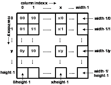 | Example: Homunculus = bright person on dark background no. of columns = width = 9, no. of rows = height = 10 |
Examples of the definition of a raster matrix M with 32-Bit color pixels = ARGB-pixel:
C++ as array : int M[height][width];
Java as array : int[][] M = new int[height][width];
C# as array : Color[,] M = new Color[height, width];
C# as bitmap: Bitmap M = new Bitmap( width, height, PixelFormat.Format32bppArgb );
Confusing, but important: All computer languages require to write first the
Consequence: If you want to blacken the mouth of the Homunculus, then write:
C++ as array : Homunculus[1][4] = 0;
Java as array : Homunculus[1][4] = 0;
C# as array : Homunculus[1,4] = Color.Black;
C# as bitmap: Homunculus.SetPixel( 4, 1, Color.Black );
Linear addressing:
A matrix is a pure language construct, because computers know only a linear address schema. Imagine the
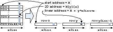 |
In main memory: At first row 0, then row 1 etc. until row |
Consequence: With millions of pixels the matrix addressing is slow.
Better: Use pointers for fast operations on images.
Example: Slow code to clear a matrix M[height][width]:
for ( y=0; y < height; y++ )
for ( x=0; x < width; x++ )
M[y][x] = 0;
Example: Fast code to clear a matrix M[height][width]:
int* pointer = M;
for ( i=0; i < width*height; i++ ) *pointer++ = 0;
Example: Very fast code to clear a matrix M[height][width]:
for ( int* pointer = M; pointer < M + width*height; ) *pointer++ = 0;
= acronym for "Picture Element" denominates an element of the raster matrix. A matrix accommodates just one type of pixel, but many types = pixel formats exist.
Samples:
| 1bppIndexed | 1 bit per pixel with indexed color. Requires a LUT with 2 colors in it. For binary images. |
| 4bppIndexed | 4 bits per pixel, indexed. Requires a LUT with 3x16 palette entries. |
| 8bppIndexed | 8 bits per pixel, indexed. Requires a LUT with 3x256 palette entries. |
| 16bppGrayScale | 16 bits per pixel. The color information specifies 65536 shades of gray. |
| 16bppRgb555 | 16 bits per pixel; 5 bits each are used for the red, green, and blue components. The remaining bit is not used. |
| 24bppRgb | 24 bits per pixel; 8 bits each are used for the red, green, and blue components. |
| 32bppArgb | 32 bits per pixel; 8 bits each are used for the alpha, red, green, and blue components. |
| 32bppRgb | 32 bits per pixel; 8 bits each are used for the red, green, and blue components. The remaining 8 bits are not used. |
| 64bppArgb | 64 bits per pixel; 16 bits each are used for the alpha, red, green, and blue components. |
False Color Image = generic term for the first 3 formats 1bppIndexed, 4bppIndexed und 8bppIndexed.
Gray Value Image = 16bppGrayScale.
True Color Image = generic term for all other formats.
Usual pixel formats are:
1bppIndexed → for binary images and b/w-printers, being quite space saving.
32bppRgb → for color photos, because 32bpp fits to the 32-bit memory architecture and 32-bit addressing of PCs.
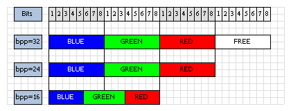 |
3 Memory Layouts of a Pixel: 32bppRgb, 24bppRgb und 16bppRgb555 Imge by Thomas Schedl |
Main differences
| Vector Graphics | Raster Graphics | |
| main data structure | Polygon: PointF[] p = new PointF[n]; | Matrix: Bitmap bmp = new Bitmap( width, height, PixelFormat.Format32bppRgb ); |
| other data structures | rectangle, ellipse, Bézier curve, spline, mesh | RLC, Crack Code, MPEG |
| file formats | WMF, PostScript, XAML, PDF, Flash, X | BMP, GIF, JPEG, MPEG, PNG, TIFF, AVI |
| memory consumption | minimal: n*sizeof(PointF) | enormous: width*height*sizeof(Color) |
| capability to draw lines | very good | with CRTs horizontal only , with flat panels horizontal and vertical, but never oblique |
| capability to fill areas | hatching only | good, but with jagged borders |
| capability to writing | too lean, but good for scalable outlinings = one font for all sizes = TrueType | good, but with jagged borders, needs a font for every size |
| capability to pictures of the real world | null, outlines only | good = TV |
| capability to produce colors | CRTs almost ever monochrome, maximal 2 colors possible | good: almost ever RGB |
| produced by | always a human being | almost always a machine: a) real world digital images (camera, scanner) b) rendered from vector graphics (graphic board) |
| mathematics | all laws of analytic geometry apply | new digital geometry necessary |
| flickering, refresh | flickers only when polygons have too many vertices | independent from picture content |
| ability to drawings | CAD, Comics | texts, images |
| volatile output | RA-CRT = vector display | line-CRT, flat panel display = raster display |
| durable output | plotter | printer |
Comparison of the operations scroll, zoom, rot
| scroll, zoom, rot of polygon p0 → p1 | scroll, zoom, rot of bitmap bmp0 → bmp1 |
| all x, y are floats | all x, y are integers |
| steplessly | only integer steps |
| always highly precise | nearly always with rounding errors |
| forward transformation from p0 to p1: transform each vertex from p0 to p1 | back transformation from bmp1 to bmp0: replace each bmp1-pixel by a pixel from bmp0 |
| there is no image border | big problem: losses by clipping |
| completly reversible | operations hardly ever reversible |
| operations are cascadeable | operations must always start from the original bmp0 |
| p0 can be overwritten by p1 | normally bmp0 must be preserved, do not overwrite by bmp1 ! |
Code comparison of scroll (translations: float dx, float dy)
| Vector-Scroll of Polygon p0 → p1 | Raster-Scroll of Bitmap bmp0 → bmp1 |
for all vertices 0 <= i < n
{ p1[i].x = p0[i].x + dx;
  p1[i].y = p0[i].y + dy;
} |
int idx = Convert.ToInt32( dx );
int idy = Convert.ToInt32( dy );
for ( int y1=0; y1 < bmp1.Height; y1++ )
{ int y0 = y1 - idy;
  if ( y0 < 0 || y0 >= bmp0.Height ) continue; //outside
  for ( int x1=0; x1 < bmp1.Width; x1++ )
  { int x0 = x1 - idx;
    if ( x0 < 0 || x0 >= bmp0.Width ) continue; //outside
    Color color = bmp0.GetPixel( x0, y0 );
    bmp1.SetPixel( x1, y1, color );
  }
} |
Code comparison of Zoom (scalings: float zoomx, float zoomy)
Center of zoom = origin of the coordinates
| Vector-Zoom of Polygon p0 → p1 | Raster-Zoom von Bitmap bmp0 → bmp1 |
//center (0/0)
for all vertices 0 <= i < n
{ p1[i].x = p0[i].x * zoomx;
  p1[i].y = p0[i].y * zoomy;
} |
for ( int y1=0; y1 < bmp1.Height; y1++ )
{ int y0 = Convert.ToInt32( y1 / zoomy );
  if ( y0 < 0 || y0 >= bmp0.Height ) continue; //outside
  for ( int x1=0; x1 < bmp1.Width; x1++ )
  { int x0 = Convert.ToInt32( x1 / zoomx );
    if ( x0 < 0 || x0 >= bmp0.Width ) continue; //outside
    Color color = bmp0.GetPixel( x0, y0 );
    bmp1.SetPixel( x1, y1, color );
  }
} |
Code comparison of Rotation (by α degrees clockwise around the origin)
| By α-Rotation of Polygon p0 → p1 | By α-Rotation of Bitmap bmp0 → bmp1 |
//center of rotation (0/0)
double arcus  = alpha * 2 * Math.PI / 360;
float sinus   = (float)Math.Sin( arcus );
float cosinus = (float)Math.Cos( arcus );
for all vertices 0 <= i < n
{ p1[i].x = p0[i].x * cosinus
          - p0[i].y * sinus;
  p1[i].y = p0[i].x * sinus
          + p0[i].y * cosinus;
} |
double arcus  = alpha * 2 * Math.PI / 360;
float sinus   = (float)Math.Sin( arcus );
float cosinus = (float)Math.Cos( arcus );
for ( int y1=0; y1 < bmp1.Height; y1++ )
{ float y1_sinus   = y1 * sinus;
  float y1_cosinus = y1 * cosinus;
  for ( int x1=0; x1 < bmp1.Width; x1++ )
  { int x0 = Convert.ToInt32( x1 * cosinus + y1_sinus );
    if ( x0 < 0 || x0 >= bmp0.Width ) continue;
    int y0 = Convert.ToInt32( -x1 * sinus + y1_cosinus );
    if ( y0 < 0 || y0 >= bmp0.Height ) continue;
    Color color = bmp0.GetPixel( x0, y0 );
    bmp1.SetPixel( x1, y1, color );
  }
} |
Annotation to raster rotation:
The Graphics-class of .NET contains an elegant variant of the method
See: http://msdn.microsoft.com/library/....
You find such a rotation animation where the vertices of the triangle slide along the window borders here: ../../C_IPCis/C1_Bitmap/CIPCisBitmap_e.htm#a9.
| Home | Contents | << Prev. | Next >> |